Manual
STEP Information screen
ST2150-POE / ST2150B-DCE
Edition 1
Content
3.3 Connecting Door environment
4 Information screen walkthrough
5 Widget explanation
1.Introduction
This article provides instructions for setting up, installing, using and maintaining the ST2150 information screen.
2.Overview
Following is an overview of the information screen.
Front
Back POE
Back DCE
Mounting plate
2.1 Connections
DCE
| PIN | Description |
| (1) + | Power input |
| (2) - | Power input |
PoE
| PIN | Description |
| (1) RJ45 | Ethernet input and power |
3 Installation
WARNING: Only power on the ST2150 once you have carefully read and
understood these instructions and confirmed that the unit is properly connected.
Failure to follow these instructions may result in damage to the product and
render it inoperable.
3.1 Cabling
3.1.1 PoE cabling
The network cable this is required to be at least CAT6 and connect the information screen with an internet connected switch. This cable provides Ethernet connectivity for two-way communication between the unit and the Cloud. If you crimp you own cable it is recommended to test the Ethernet cable with at network tester to confirm it is working correctly.
3.1.2 Standard wiring PoE
3.1.3 Tools, Cables and plugs PoE
Being well-prepared with the necessary equipment can facilitate a smooth
and efficient setup, reducing the likelihood of encountering issues or delays.
Some of the tools you may want to have on hand for a seamless installation
Include:
• A high-quality RJ45 termination tool is indispensable for a successful installation.
This tool guarantees a secure and accurate termination of the CAT6 cable to the RJ45 plug, which is vital for establishing a stable and reliable connection between the power supply and the ethernet switch
• An RJ45 network cable tester is essential for evaluating the CAT6 cable after termination. This instrument helps verify that the cable has been correctly terminated and is functioning as intended, ensuring the integrity of the connection.
Note: It's essential to use high-quality RJ45 plugs for secure and accurate terminations, as this contributes to stable and reliable connections. Be sure to use short plugs to maintain optimal performance and connectivity.
3.1.4 DCE Cabling
When installing DCE (DC Ethernet), it is critical to ensure that the cabling used has sufficient capacity to handle the current required by the equipment at the other end of the cable.
To ensure optimal performance, the following should be considered:
- The cabling must be sized to deliver the required current without voltage drop or overload.
- Avoid unnecessary splices in the cabling. Poor connections can cause voltage loss and disrupt signal transmission, which may negatively affect network speed.
3.1.5 Standard wiring DCE
Note: Remember when use existing wires keep attention to the amount of power that can be transferred on a special cable size.
By following these guidelines, a stable and efficient DCE installation can be achieved.
The table below provides a general indication of the current capacity for cables with different conductor cross-sections. Please note that this is only a guideline. Proper sizing requires a calculation based on the specific conditions of the actual installation site.
Table 1 – Reference Values for Maximum Current Draw in Copper Cables
| Length (meters) | 0,22 mm² | 0,3 mm² | 0,5 mm² | 1 mm² |
|---|---|---|---|---|
| 50 m | 0,45 A | 0,62 A | 1,03 A | 2,06 A |
| 100 m | 0,23 A | 0,31 A | 0,51 A | 1,03 A |
| 150 m | 0,15 A | 0,21 A | 0,34 A | 0,69 A |
| 200 m | 0,11 A | 0,15 A | 0,26 A | 0,51 A |
3.1.6 Tools, Cables and plugs DCE
Being well-prepared with the necessary equipment can facilitate a smooth
and efficient setup, reducing the likelihood of encountering issues or delays.
Some of the tools you may want to have on hand for a seamless installation:
Include:
• A high-quality cable cutter tool is needed for a successful installation.
• A flat screwdriver sized 2-3mm.
• A multimeter for troubleshooting and verification.
3.2 Physical installation
NOTE: It is crucial to verify that all cables are installed properly and
securely to prevent any potential complications or errors during the installation process.
It is recommended to visually inspect all cables and use a network tester to confirm
that the cables are in good working condition before proceeding with the installation.
This will help to prevent any potential issues that may arise due to faulty or improperly
installed cables.
3.2.1 Placement
ST2150 come with a mounting plate for wall mounting.
We recommend a height of approximately 1400 mm from finished floor to center of screen. This provides a good height for the majority of users. However, we recommend that you install the height as agreed with the customer.
3.2.2 Instructions
- To mount the information screen on the wall, start with unlocking the hatch that is placed on the bottom of the information screen with the keys that comes with the package.
- After opening the hatch, you can start removing the screw that holds the mounting plate fixed.
- After removing the screw, you can slide the mounting plate off.
- Use the following plugs and screws received with you package and mount the mounting plate at the desired spot on the wall.
- Ensure the plate is fitted tightly and secure against the wall before you take the information screen and slide it from the top down on to the hooks of the mounting plate.
- Always secure the information screen against the mounting plate with the screw inside the hatch.
- Lock the hatch and store the keys to the information screen in the secure and accessible location.
3.3 Connecting Door environment
Example with POE+ as power and data source. The integration between the door controller and the information screen is done through StepLock Cloud, and it's the same for both POE+ and DCE communication.
4 Information screen walkthrough
Starting screen with meny area, register and widgets
4.1 News
Internal news
Click on a article to read it
4.2 Documents
Upload documents
The files are interactable, you can scroll up and down, zoom in and out
4.3 Contacts
Upload contacts
4.4 Links
Links to websites
The websites are fully interactable
4.5 Booking
Your active bookings
Edit your bookings
Shoose a booking object
When your booking has started, press the lock button on the infromations screen to open your booking object
5 Widget explanation
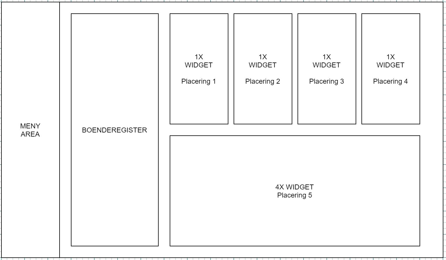
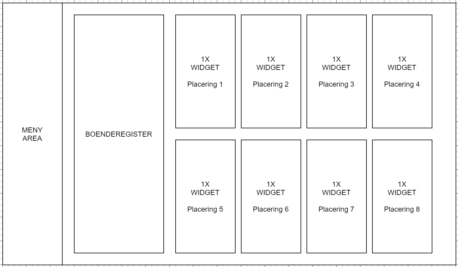
When creating a widget, these can be placed on the screen and sorted in numerical order. Widgets are available in different sizes, currently 1x (standard size) and 4x (takes up 4 standard dimensions) placement is shown in the example illustrations below.
Example with 8pcs 1x widget
Example with 4x 1x widgets and 1x 4x widget