
Manual
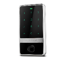
ST2008 (C61) Card reader
Content
- Components
- System Overview
- Switch-on door box
- Connecting card reader
- Installation
- Booting
- Specification Cabling
1.Components
A complete starter kit includes the following components.
- Card reader
- Door box ST2043-POE
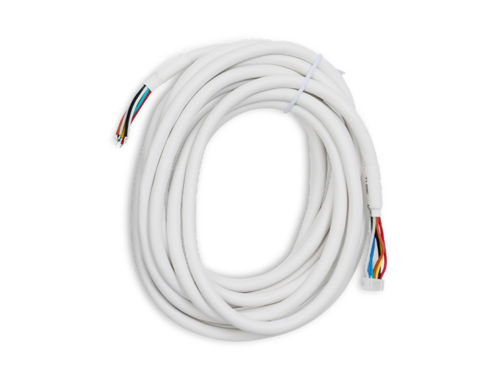
- Connection cable (door box <-> card reader)
| 1 | 2 | 3 |
 |
 |
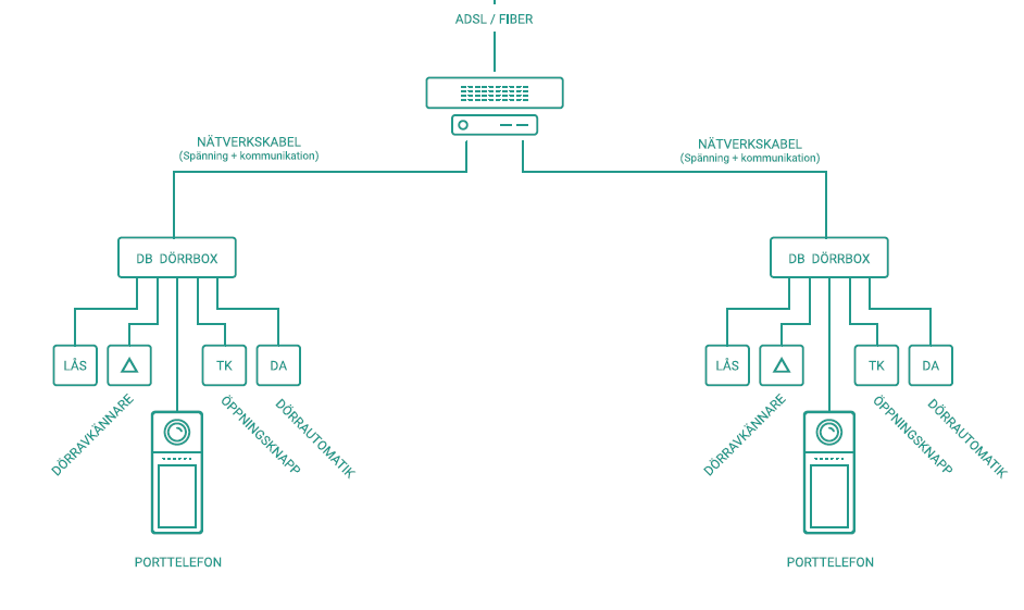
2. System Overview
3. Connection door box
Refer to the ST2043-POE or ST2043-LTE manual
4. Connecting card reader
The U8 Reader serves as the primary input component for the main card reader, facilitating seamless data transfer and processin
This input features a color-coded connection pin system to ensure proper configuration and functionality.
The pins are assigned as follows:
- Red: This pin is responsible for providing 12 volts of power to the card reader.
- Black: This pin acts as a ground connection and provides a stable reference point for the electrical circuit.
- Yellow: The tamper pin detects unauthorized access or tampering with the card reader, ensuring optimal security.
- Brown: This pin is connected to the buzzer, which provides audible alerts or messages during operation.
- Green: The D0 pin is responsible for managing data communication between the card reader and the connected device.
- White: Similar to the green pin, the D1 pin also handles data communication, allowing for efficient data processing.
- Blue: This pin is connected to the red LED, which acts as an indicator light for different operating statuses.
- Gray: The gray pin is connected to the green LED, which also serves as a status indicator for the card reader.
5. Installation
-
Install the door box near the door in question. Connect the network cable that has just been placed with an RJ45 connector at both ends according to standard T568B, see picture below.
- Measure out the recommended installation height for the card reader, (1150mm) from the ground and run the connection cable between .
- Plug in and mount the card reader to the wall.
- Connect the card reader cable to the door box in the 8 pin connector.
- Plug the RJ45 connector into the door box.
- If everything is connected correctly, the diode on the circuit board will light up.
- Pull in the electric-lock cable to the door box and connect on the screws marked LOCK.
- If the Open button is used, connect this to the input marked OPEN BUTTON.
6. Startup
When the installation is complete, it is time to start up the card reader.
- Plug the power plug into the card reader.
- If the card reader is connected to the door box in connection with the start-up of the door box, it will light up red and beep with the buzzer, this is completely normal.
- When the card reader is connected, it will start with two beeps. then it should go out and flash every 5 seconds.
- Now the local start-up is complete and the rest of the installation takes place in the StepLock Cloud.
7. Specification of cabling
- Cable between card reader and door box must be straight wired cable 0.3 mm2 (5m finished cable included)
Important: If a twisted pair cable is used, problems with communication between the card reader and the door box may occur. If another cable cannot be used, connect D0 and D1 in different pairs.